Compaction
Compaction is the greatest determining factor in dense graded pavement performance (Scherocman and Martenson 1984; Scherocman 1984; Geller 1984; Brown 1984; Bell et. al. 1984; Hughes 1984; Hughes 1989). Inadequate compaction results in a pavement with decreased stiffness, reduced fatigue life, accelerated aging/decreased durability, rutting, raveling, and moisture damage (Hughes, 1984; Hughes, 1989).
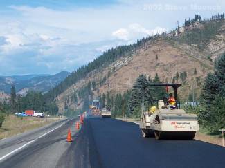
Figure 1: Rollers at Work
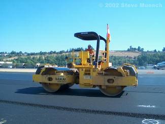
Figure 2: Rollers at Work
Compaction Measurement and ReportingCompaction reduces the volume of air in HMA. Therefore, the characteristic of concern is the volume of air within the compacted pavement, typically quantified as a percentage of air voids by volume and expressed as “percent air voids”. Percent air voids is calculated by comparing a test specimen’s density with the density it would theoretically have if all the air voids were removed, known as “theoretical maximum density” (TMD) or “Rice density” after the test procedure inventor.
Although percent air voids is the HMA characteristic of interest, measurements are usually reported as a measured density in relation to a reference density. This is done by reporting density as:
- Percentage of TMD (or “percent Rice”). The expression of density is easy to convert to air voids because any volume that is not asphalt binder or aggregate is assumed to be air. For example, a density reported as 93 percent Rice means that there are 7 percent air voids (100% – 93% = 7%).
- Percentage of a laboratory-determined density. The laboratory density is usually a density obtained during mix design.
- Percentage of a control strip density. A control strip is a short pavement strip that is compacted to the desired value under close scrutiny then used as the compaction standard for a particular job.
WAPA Pavement Note on Compaction Reporting
WSDOT reports compaction as a percentage of TMD and therefore, most other agencies and owners tend to use this reporting method as well.
Pavement air voids are measured in the field by one of two principal methods:
- Cores (Figure 3). A small pavement core is extracted from the compacted HMA and sent to a laboratory to determine its density. Usually, core density results are available the next day at the earliest. This type of air voids testing is generally considered the most accurate but is also the most time consuming and expensive.
- Nuclear gauges (Figure 4). A nuclear density gauge measures in-place HMA density using gamma radiation. Gauges usually contain a small gamma source (about 10 mCi) such as Cesium-137 located in the tip of a small probe, which is either placed on the surface of the pavement or inserted into the pavement. Readings are obtained in about 2 – 3 minutes.
Each contracting agency or owner usually specifies the compaction measurement methods and equipment to be used on contracts under their jurisdiction.
WAPA Pavement Note on Compaction Field Measurement
WSDOT uses nuclear gauges to measure compaction for use in contract payment. Nuclear gauges are always calibrated to core density measurements.
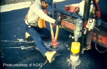
Figure 3: Core Extraction
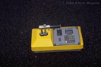
Figure 4: Nuclear Density Gauge
Factors Affecting Compaction
HMA compaction is influenced by a myriad of factors; some related to the environment, some determined by mix and structural design and some under contractor and agency control during construction (see Table 1).
Table 1: Factors Affecting Compaction
| Environmental Factors | Mix Property Factors | Construction Factors | |||||
| Temperature | Aggregate | Rollers | |||||
| Ground temperature Air temperature Wind speed Solar flux |
Gradation Size Shape Fractured faces Volume |
Type Number Speed and timing Number of passes Lift thickness |
|||||
| Asphalt Binder | Other | ||||||
| Chemical properties Physical properties Amount |
HMA production temperature Haul distance Haul time Foundation support |
||||||
Compaction Equipment
There are three basic pieces of equipment available for HMA compaction: (1) the paver screed, (2) the steel wheeled roller and (3) the pneumatic tire roller. Each piece of equipment compacts the HMA by two principal means:
- By applying its weight to the HMA surface and compressing the material underneath the ground contact area. Since this compression will be greater for longer periods of contact, lower equipment speeds will produce more compression. Obviously, higher equipment weight will also increase compression.
- By creating a shear stress between the compressed material underneath the ground contact area and the adjacent uncompressed material. When combined with equipment speed, this produces a shear rate. Lowering equipment speed can decrease the shear rate, which increases the shearing stress. Higher shearing stresses are more capable of rearranging aggregate into more dense configurations.
These two means are of compacting HMA are often referred to collectively as “compactive effort”.
Paver Screed
Approximately 75 to 85 percent of TMD will be obtained when the mix passes out from under the screed (Figure 5) (TRB 2000).

Figure 5: The mat is about 75 – 85 % of TMD when it comes out behind the screed.
Steel Wheel Rollers
Steel wheel rollers are self-propelled compaction devices that use steel drums to compress the underlying HMA. They can have one, two or even three drums, although tandem (2 drum) rollers are most often used. The drums can be either static or vibratory and usually range from 35 to 85 inches in width and 20 to 60 inches in diameter. Roller weight is typically between 1 and 20 tons (Figures 6 and 7).
Some steel wheel rollers are equipped with vibratory drums. Drum vibration adds a dynamic load to the static roller weight to create a greater total compactive effort. Drum vibration also reduces friction and aggregate interlock during compaction, which allows aggregate particles to move into final positions that produce greater friction and interlock than could be achieved without vibration. As a general rule-of-thumb, a combination of speed and frequency that results in 10 – 12 impacts per foot is good. At 3000 vibrations/minute this results in a speed of 2.8 – 3.4 mph. Newer steel wheel rollers can also be equipped with “oscillating” drums, which are essentially vibrating drums with a more circular (rather than up-and-down) motion.
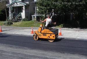
Figure 6: Small Static Steel Wheel Roller 1.45 tons, 34-inch wide drum
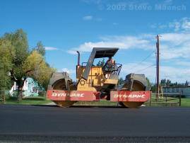
Figure 7: Large Vibratory Steel Wheel Roller 18.7 tons, 84-inch wide drum
Pneumatic Tire Rollers
Pneumatic tire rollers are self-propelled compaction devices that uses pneumatic tires to compact the underlying HMA. Pneumatic tire rollers employ a set of smooth (no tread) tires on each axle; typically four or five on one axle and five or six on the other. The tires on the front axle are aligned with the gaps between tires on the rear axel to give complete and uniform compaction coverage over the width of the roller. Compactive effort is controlled by varying tire pressure, which is typically set between 60 and 120 psi (TRB, 2000). In addition to a static compressive force, pneumatic tire rollers also develop a kneading action between the tires that tends to realign aggregate within the HMA. Because asphalt binder tends to stick more to cold tires than hot tires, the tire area is often insulated with rubber matting or plywood to maintain the tires near mat temperature while rolling (Figures 8 and 9). Some newer pneumatic tire rollers can be equipped with vibrating or oscillating wheels.

Figures 8: Pneumatic Tire Rollers
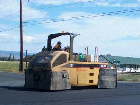
Figures 9: Pneumatic Tire Rollers
Roller Variables
There are several variables associated with rollers that can be adjusted from job to job such as:
- The sequence and number of rollers.
- Roller speed.
- The number of roller passes over a given area of the mat.
- The location at which each roller works.
- The pattern that each roller uses to compact the mat.
Not all these variables are infinitely adjustable, but by adjusting a combination of them a rolling plan can be developed that will optimize mat compaction.
Construction


